Page History: Assembling a Delta Lathe Compound Slide Rest
Compare Page Revisions
Page Revision: 2008/11/30 17:13
by Bill NanceIntroduction
This page shows the process and parts involved in assembling a compound slide rest for a Delta 12" wood lathe. The part numbers referenced in this page are taken from a manual #PM-1533, dated 1/15/1948. Reprints of that manual can be found at:
Delta Compound Slide Rest Manual #PM-1533.
While one might expect the reassembly to start with the sub-base, that is actually the final step and will be covered at the end of this tutorial. Access is needed inside the base, so instead, we start with the base and lower feed screw.
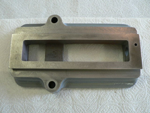
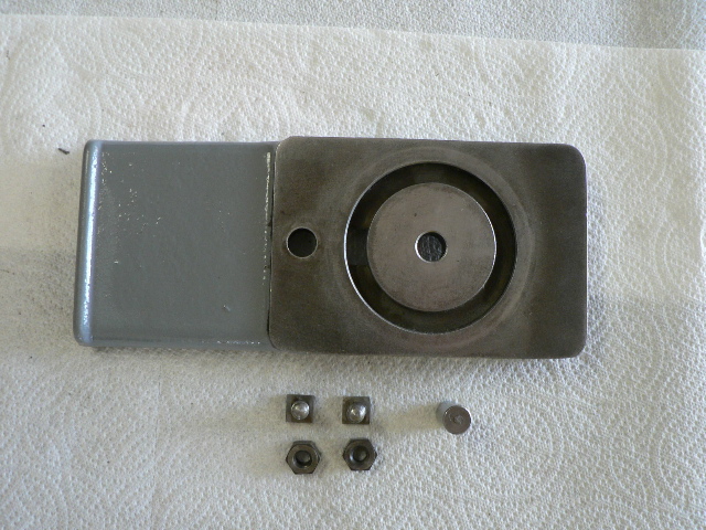
Base, DDL-226-R
The lower feed screw assembly is installed within the base.
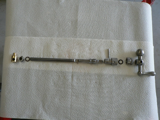
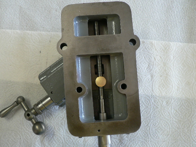
Exploded parts of Lower Feed Screw assembly, DDL-233-S
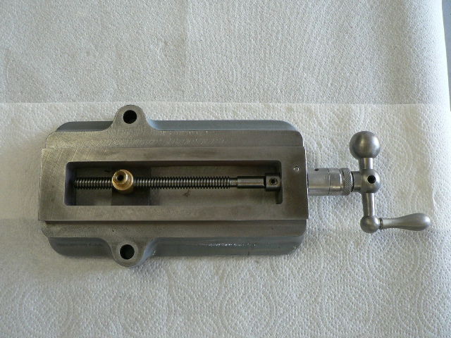
Lower Feed Screw assembly installed in Base
After assembling the base and lower feed screw, the next step is to install assemble the upper feed screw within the upper slide.
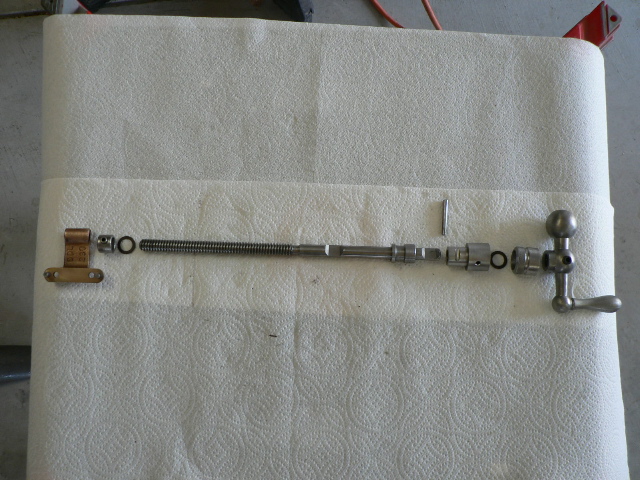
Exploded parts of Upper Feed Screw Assembly, DDL-232-S
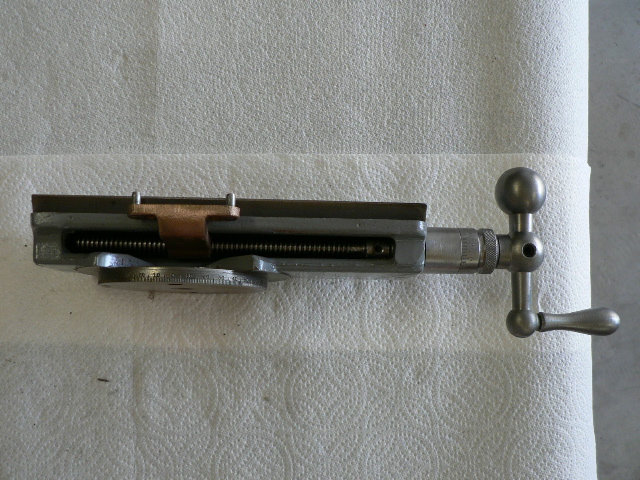
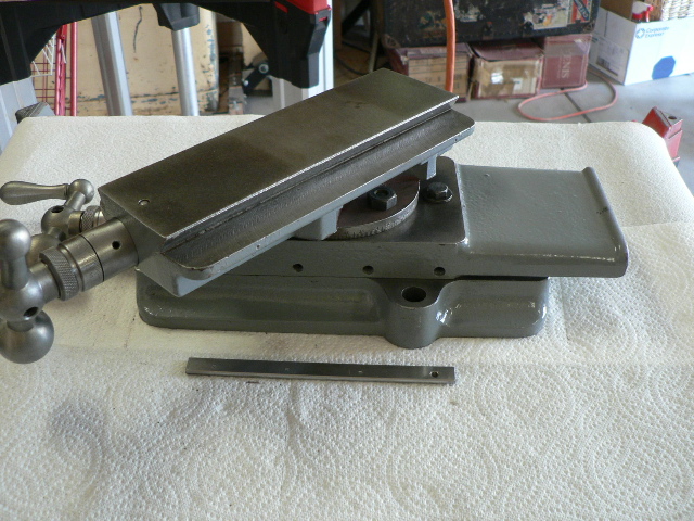
Upper Feed Screw installed in Upper Slide, DDL-229
Once the two slide mechanisms are assembled, they are attached using the swivel saddle. A post extends through the saddle into the calibrated lower cylinder on the upper slide,
Top view of lower slide, swivel saddle, and upper slide assembled
with square-head T-bolts installed in the saddle slots.
Swivel Saddle, DDL-228-R
Bottom view of lower slide, swivel saddle, and upper slide assembled