Page History: J. A. Vance No. 2 ½ Planer Matcher Restoration
Compare Page Revisions
Page Revision: 2015/10/18 21:07
Foreword
This restoration was originally chronicled on the
The Iron Giants: Matcher Resto Race of 2012! on the Old Woodworking Machines Forum.
The Vance 2½ planer matcher was Keith Rucker’s entry into a completion to see who could restore their planer-matcher first.
The Restoration
Jun 03, 2012 - The matcher that I will be working on does not actually belong to me - it is in the collection of our local museum - the Georgia Museum of Agriculture (formally the Agrirama) in my home town of Tifton, GA. I am going to have to see if I can find some history on this machine from the curator. For at least ten years, this machine sat outside near the museums "bone yard". About four years ago, during an attempt to get the museum’s collections better organized, she got moved under a storage building where she now sits. I have looked at this machine many times over the years as a candidate for restoration, she is for the most part all there and there does not appear to be anything major wrong with her.
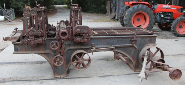
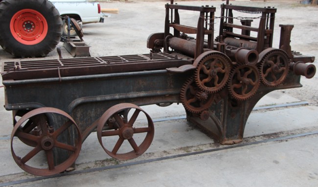
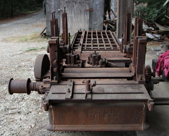
The machine that I am talking about is a J. A. Vance No. 2 1/2 Planer Matcher. She basically has four heads - two to plane the top and bottom of a board as it passes through and then two side heads that can either joint the board square or mold a profile on the edge. Commonly, these machines were set up to run tongue and groove such as flooring or panelling all in one pass. Here are some pictures that I took of the machine and uploaded to the Photo-Index on VintageMachinery.org back in 2008: I do seem to recall that there are a few issues with this machine that will make restoration more difficult (but not impossible), I just don't recall exactly what they are. Hopefully this week, I will be able to find some time to run out to the museum and go over her more closely - I will report back then with more information on the machine.
I am looking forward to getting started on this project. While this will not be my first restoration of an antique flat belt machine, this would have to be one of the largest machines I have ever taken on as a restoration project.
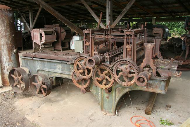 Side View of Vance 2½ Planer Matcher |
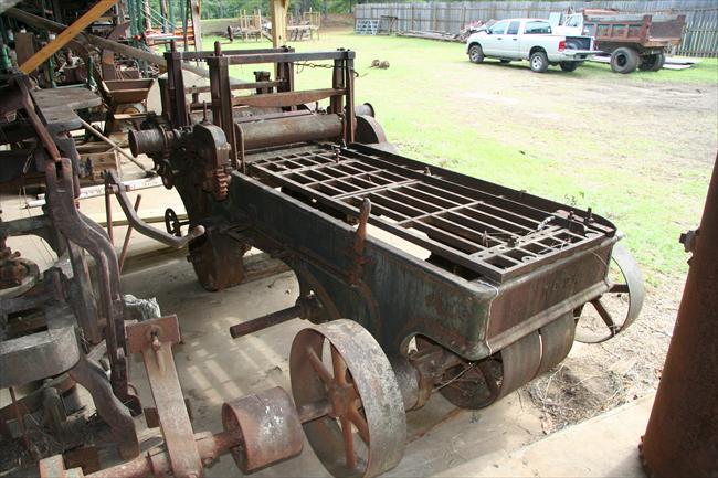 End View of Vance 2½ Planer Matcher |
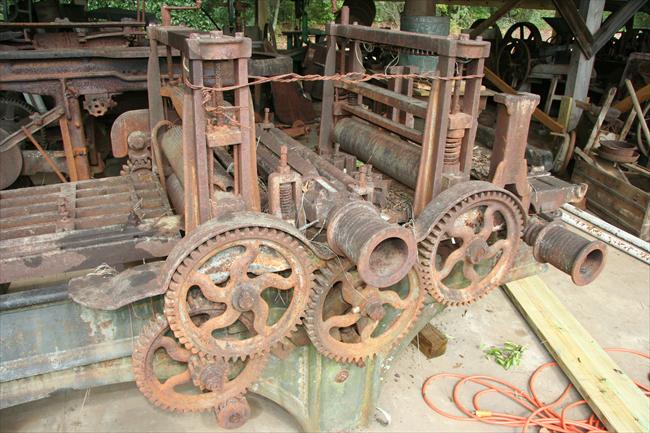 View of Drive Gearing for Vance 2½ Planer |
Jun 05, 2012 - I got out to the museum late this afternoon to take a closer look at the Vance matcher. It has been several years since I have looked at here real close and I remembered that there were some issues with the machine, but I could not recall what all they were. For full disclosure of the problems I will have to overcome, here are what I now consider "known issues" with the machine (and I am sure that I will uncover plenty more when I start digging into this machine):
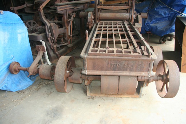 Bent Countershaft and broken pulley |
At some point in time (probably when moving it to the museum), the contershaft on the machine was bent. While not a major problem from the stand point of being able to fix it, the shaft is a pretty large diameter and a good six to seven feet long. Bottom line is that it will be expensive to replace. While I might be able to bend it back straight again, it is so rusted anyway, I will probably just replace. Coupled with the fact that one of the pulleys on this shaft is broken and will need to be replace, I doubt that I would ever be able to get the broken pulley off (along with the ones in its way that will need to be removed to replace it) with the shaft as rusty and pitted as it is. Additionally, I will need to find a replacement pulley for the one that is broken.
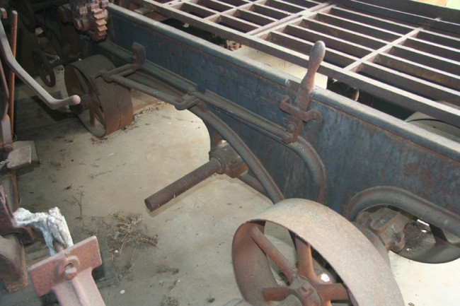 Missing Pulley |
Here you see a shaft sticking out from the left side of the machine. I am sure that there is supposed to be a pulley on this shaft - I will have to figure out what size it needs to be and find a replacement.
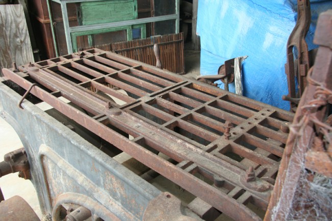 Missing Guide |
You can see the guide on the right side of the infeed table. There should also be a guide on the other side that could be adjusted depending on the width of the board being fed into the machine (there are multiple holes in the table to bolt it in place). Of course this guide is MIA - I will need to find out (or possibly imagine) what this looked like and make a pattern to have a new guide cast.
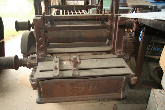 Missing Rollers |
In this picture, you see the two uprights at the rear of the machine. These are located directly over the cutter-head that planes the bottom of the board going through the machine. I can only assume that there is a pressure roller that should fit into these uprights to hold the board down as the cutter-head planes the bottom of the board. All that is there are the uprights - I will have to probably imagine how this was all put together and totally re-build this from castings/steel. Also, there are two "hooks" on the very end of the machine - I can only assume that there is a roller that fits into these hooks for the boards coming out of the machine. Again, I will probably have to imagine how this was originally and turn something to work on the lathe.
While the issues that I uncovered today are all by no means minor, it does appear that the rest of the machine is for the most part there - including all four heads. The good news is that I did not see any broken parts that will need to be repaired or replaced. One issue that I do see is that the steel parts on the machines (shafting, heads, rollers, nuts, bolts, etc.) are all severely rusted and pitted. Many, if not most, of these parts will need to be totally replaced. The good news is that the cast iron parts (the majority of the machine) appear to be in pretty good shape all things considered. And, as I said before, I am sure that I will uncover many other unknown problems as I dig into this restoration.
Quite honestly, this is one of my biggest concerns on this restoration - the lack of reference information on J. A. Vance. I spent several hours this past weekend trying to dig up anything I could find on this company as well as any articles, advertisements, catalogs, etc. Unfortunately, my search was not very fruitful. While I was able to add a bit more information on the history of the company history on the Vintage Machinery site, as far as this machine is concerned, nothing really turned up. There are some pictures of a very similar machine to this one (a No. 2 ½ B as compared to my No. 2 ½) in the VintageMachinery.org Photo Index - I am hopeful that I will be able to contact the owner of that machine to use as a reference.
Jun 06, 2012 - On yours I think we may severally be missing what I believe to be a spring lever on the infeed table. Pivoting at one set of holes and locking over pins in the other set. There are few good illustrations and I have mostly seen homemade metal spring set ups. Early ones look like wood. Springy wood.
Here is a picture of a similar Vance No. 2 ½ B (mine is just a No. 2 1/2 - no "B") in the VM Photo Index:
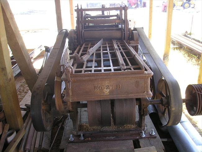 Vance No. 2 ½B Infeed Table Rollers |
That very well could be a spring bar.
Another strong possibility. Here is a picture from the same machine above showing what looks like a pressure plate:
[imageauto| Vance No. 2 ½B Pressure Plate |GetFile.aspx?File=/J. A. Vance No. 2 ½ Planer Matcher Restoration/fig. 08.jpg
When I first saw it, I assumed that the roller was missing on this one as well. After your suggestion that it might be a pressure plate, I think that is exactly what was there.
I need to contact the owner of this machine and see if he will let me borrow a few parts to use as patterns to have new parts cast. If not, maybe I can get drawings so that I can make patterns and have parts cast.
Jun 07, 2012 - Fortunately, I can do my own machining since I either own or have access to lathes, mills and other machine shop equipment. My experience with casting is that it is not terribly expensive (through Cattail), but multiple parts can sure add up in a hurry. As to knives, I have made my own out of A2 steel on my milling machine and had them hardened locally, but even then, the A2 is pretty darn expensive - I think I had about $200 tied up in the set of two knives I made for the 24" Fay and Egan planer last year. Cutterhead bolts will also be expensive - I have a few new ones on hand, but not enough for the project (and all of the bolts on my machine will need to be replaced). For me, I think that the most expensive part of this project will potentially be belting if I have to purchase new - hopefully, I will be able to recycle most of the belting from the museums stash.
If I am able to finish this project for only $1,000, I think I will be doing real good. Normally, I don't do a good job of keeping up with expenses on a restoration (I usually don't really want to know). For this project, I think I will try and keep good records of both time and money spent on the restoration.
Jun 08, 2012 - Well, today has been a very productive day in researching the Vance matcher. I reported the other day that I found reference to a 1911 J. A. Vance catalog in the Smithsonian Library. A fellow member here (I will let him tell who it is if he likes) contacted me and told me that he was going to DC in the next few weeks and would volunteer to stop by and try and get copies of the catalog for me. I sent him the information on the book with a big smile on my face. In the meantime, he contacted the Smithsonian to find out what he would need to do in order to gain access, and the person there instead said that she would just scan a copy for him and save him the effort! So, today, I got scanned copies of the catalog (which is now also uploaded to the VM site - 1911 J. A. Vance Catalog)
Unfortunately, the catalog had four pages missing, and of course, one of those pages was the cut of the No. 2 1/2. But, there were cuts of the No. 3 and No. 3 1/2 - both of which were identical except for the number on the side of the machine and both look identical to my No. 2 1/2. I strongly suspect that the cut for the No. 2 1/2 was also the same. Here is what was in the catalog related to my matcher:
This will be of great help! The description gives me some critical information such as countershaft RPM, HP requirement and even the length of the belts required. It also shows some of the missing parts on my machine which will be very helpful as I try to reproduce them.
10 Jun 2012-While out at the museum this weekend, I went and made some measurements on the pulleys and shafts that will need to be replaced on the Vance. Here is a short list of what I know that I will need in case anybody has something in their rathole looking for a home.
The broken pulley on the countershaft is 8-inches in diameter, 6-inches wide, and fits a 2-inch diameter shaft.
The missing pulley on the left side of the machine should match the one that is there on the right - it measures 17½-inches in diameter, 5-inches wide and also fits a 2-inch diameter shaft. This missing pulley needs to be an exact match to the one that is there so the odd-ball size diameter of 17½-inches is an absolute need.
Both of these shafts will also need to be replaced - they are both 2" in diameter by 6-foot and 8-foot long respectively.
14 Jun 2012-I squirted two cans of PB Blaster on my machine today. Hardly got it wet....
23 Jun 2012-While out at the museum yesterday afternoon, I shot some video of the Vance Matcher. Take a video tour of the matcher here:
Vance Matcher Video
23 Jun 2012-Well, I know that I told several of you at ArnFest last week that it would probably be November before I would have a chance to get started on the museums matcher. But sitting here reading all of these posts and seeing progress being made by my competitors, I just could not stand by and let anybody get too far ahead of me. So, today, I decided to blow off all of the things that I need to be doing and instead spent the day out at the museum getting started on my machine.
The first order of business was to move the big matcher from the storage building it has been residing in out to the shop area where I can properly work on it. This was no small task in itself - seeing as this machine weighs in at about 2 1/2 tons, she is not as easy to move around as a lot of the machines I work on. Using chains and slings, I managed to drag the big matcher from where it sat in storage to the door of the building where I could get to it with the forklift. Because of all of the pulleys and such under the machine, I did not feel good about picking it up with the forks from the bottom, so I instead used several slings to pick it up from the top side, letting it hang beneath the forks. This was SCARY to say the least - 2 1/2 tons of cast iron hanging (and swinging) from the bottom of the forks was not a lot of fun - especially since there was about 100 yards of bumpy and hilly terrain to get from the storage building to a decent dirt road to move it the rest of the way. The best part of the whole trip was when I was driving downhill a short piece and the weight of the matcher caused the back wheels of the forklift (the steering wheels) to lift off the ground! I did not have the machine very high off the ground (fortunately) and as soon as the feet touched the ground, the forklift righted itself and I was able to ease down the rest of the hill. Once I got on the road, it was not too bad.
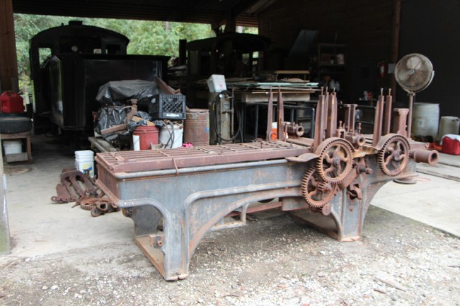
Once at the shop, I sat it down on the concrete pad outside the shop doors. I took an air hose and gave it a good air bath, blowing off years of dust, dirt, leaves, vines, and whatever else was on the machine. It must have been 20 pound lighter after the cleaning!!! Here is what she looked like before I started the tear down:
 |
 |
At this point, the game plan was to just start taking things apart - as the old joke goes, "how do you eat an elephant? One bite at a time!" - on this machine, it is "one piece at a time." The first part to come off was the big tail shaft - it was just in the way sticking out so far on one side - so it was the first pieces to remove. I was real worried at how easy the bolts would come apart on this machine - while the cast iron parts have held up well, many of the steel parts on the machine are in really bad shape. I am glad to say that so far, most of the bolts have come apart pretty easy - as was the case with the bolts holding the bearing blocks on the tail shaft.
While the bolts came off pretty easy, the condition of the bearings was nowhere near what I was hoping for. When the first bearing cap was removed, I took apart the bearing on the side of the tail shaft closest to where the shaft was bent at some point in time. Unfortunately, it soon became obvious that the Babbitt was in really bad shape and that the bearing shell casting had been broken (probably when the shaft was bent). Not a pretty sight:
I think that I can repair this break, but I might just take the good one from the other side of the shaft and send it to Cattail and have a new one cast. Either way, it should not be too bad to fix.
With that shaft off, I also removed the second shaft under the machine. This one went a lot easier and nothing appeared to be too bad. Because I will need to replace the shaft, I will probably have to re-pour the bearings, but they did not look that bad.
Next piece to go was the main cutterhead. Again, I removed the bearing caps and saw what was an all too familiar sight - the steel shafts in the babbit bearings were again rusted causing a mess. Both sides looked more or less like this:
While working on the cutterhead, I also removed the pressure bar and chip deflector, which was pretty straight forward.
Next on the agenda was taking apart the expansion gears - two sets of them on the two sets of feed rollers. To my suprise, this turned out the be the most difficult part of all day long - while the first set came off without too much trouble, I spent nearly two hours getting the second set apart - the shafts that the gears rode on were very worn, rusted, and pitted. They were in a very hard place to get two and I could not fit a punch or hammer behind them to tap them off. I ended up putting a good bit of heat on them with the torch in hopes that I could get the cast iron to expand a bit and then used various sets of cold chisels as wedges, which I drove between the various parts to separate everything. It sounds a lot easier than it was - for a while I was really wondering if I would ever get these parts apart! Persistence paid off, and after way too long and way too many swings of a pretty big hammer (I was worn out), I was finally successful.
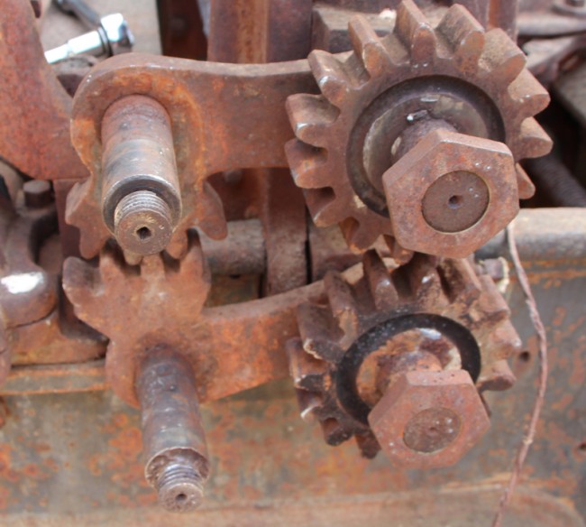 |
At the end of the day, I had spent 8 hours at the museum working on getting parts off of the machine. I was hot, dirty, sweaty, smelly (real smelly!) and nearly exhausted. It was not too bad this morning, but we hit right at 90 degrees today with pretty high humidity - the heat and hammering had really taken the life out of me. The expansion gears really slowed me down and I have to say that I was disappointed in the amount of progress that was made today. But in reality, I am glad that this part is behind me - at least I am started now and no matter when I did get started, it would have taken the same amount of time to accomplish what I did. Still a lot of parts to get taken off before I can start cleaning things up and putting them back together though...
Here is a shot of the machine with a few things removed:
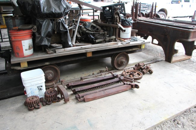
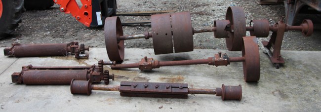
And here is a shot of everything that was taken off today:
30 Sept 2012-After looking at my competitors progress over the weekend, I could hardly sleep last night! So today, even though I did not have time, I managed to carve out a couple of hours this afternoon to sneak over to the museum and try and make a little more progress. Fortunately for me, today, things seemed to come apart easier than they did yesterday - that expansion gear mess yesterday just really bogged down my progress. Today, I managed to remove both of the top feed rollers from the machine along with a half dozen or so other little things that needed to be removed. Still a ways to go to get her stripped down, but at least she looks like some progress was actually made with the rollers gone. Here are some pictures of where we are as of now:
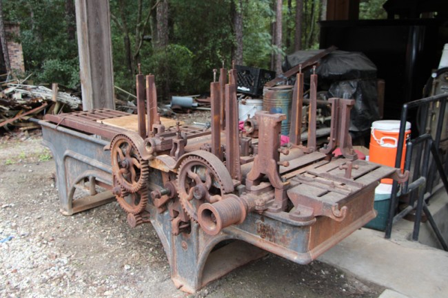 |
 |
 |
 |
 |
Next order of business will be to remove the two big gears that drive the bottom feed rollers. I am scared to death of trying to get them off - you can tell that they are really rusted in place and the key on each pulley look like they were driven in with a hammer so I am sure they are wedged in. I drilled out as much of the key stock as I could without messing up the key ways, but even then, they are still tightly in place. judging from my troubles with the expansion gears, I hate to think how bad these will be.
I am trying to come up with a good game plan on removing the gears. Because of the size of the hubs and the five curved spokes, a regular gear puller will not come close to fitting. I have in my mind a plan for how I might build a custom puller for these specific gears, but that too will eat up my precious time I have to work on this project.
I am working on this at the restoration shop at the museum. We basically have two sets of track that come in from the museum's railroad line so that we can keep our locomotives under shelter as well as have a good place to work on them. In one of the pictures, you can see the 1917 Vulcan Iron Works 0-4-0 on the left (our operational steam locomotive) and the 1924 Porter 0-4-0 on the right - a future restoration project.
As for the icing on the cake, I have not filled you guys in on that one yet. We are working on a rail cart that I can set the entire matcher on so that I can roll it in and out of the shop on the tracks - and even better - over one of the pits that we have under shop floor that will allow great access to the bottom of the matcher for working on the side heads and other parts beneath this monster! Still have a few bugs to work out of that part of the deal, but hopefully the museum staff will have that old cart pulled out of the weeds and ready for me to set it on when I get back...
06 Oct 2012- I was fortunate enough to have spent about eight hours today out at the museum working on the Vance. I had to drop my daughter off this morning at 6:00 am to get on a bus and travel to her cross country match. As long as I was up early and out of the house, I just went straight on out to the museum and got to work.
The first order of business was to remove the two big gears that drive the feed rollers. I tried last week to use a regular gear puller to get them off, but because of the way the back of the hub was shaped and the wide area around the spokes, I was unable to get them to hook behind the gear as I would like. So, this past week while I was on the road, I worked out a plan in my mind on how to get them off. I really like pressing shafts out of pulleys and such using either a hydraulic press or an arbor press, and I decided to adapt a similar method to this job. Using some 1/2-inch thick plate steel, cut out a half moon shaped piece to fit on the back of the gear and cut a a slot on the flat side to fit over the shaft. Nothing fancy, I just used a cutting torch to cut the parts out and a grinder to knock off the rough edges. I then used a piece of chalk to trace around the spokes with the piece in place to figure out where I could fit some bolts through from the front side. I then drilled and tapped four 1/2" x 13 holes to thread the bolts into. Four matching holes were drilled through a rectangular piece of steel.
My plan was to use a hydraulic jack between the center of the shaft and the back plate - which was bolted to the puller plate on the back of the gear. I quickly ran into a problem though - I had forgotten that most hydraulic jacks do not work while lying on their side. No problem though, I remembered that the museum had a hand operated hydraulic cylinder as part of a pretty cool jacking set. I had to extend my bolts longer for the cylinder to fit using threaded rod, but it was basically the same idea as before. Here are some pictures to give you an idea of how it all worked:
 |
 |
The first gear came off with little effort. The second one was a good bit more stubborn. I had really put a lot of pressure on the cylinder and nothing had moved - we had the cylinder pretty much maxed out and I was afraid that the gear would shatter at any time. So, I resorted to putting some heat on the gear with a torch. The idea being if you apply some heat to the hub on the gear, the heat would cause it the expand just ever so slightly - you of course want to heat up the outside hub without heating the shaft. After just a few seconds of applying heat, I heard a nice sounding "POP" and the gear was moving. I cut the torch off and she just came right off with little pressure from the cylinder the rest of the way.
All in all, it took me about 2 hours to build the puller and get the two gears off. Not to bad of a start for the morning!
From there, I just continued removing parts from the machine, one piece at a time. The bottom feed rollers were removed (with the help of a forklift providing the heavy lifting - each of these feed rollers alone on this machine weigh on more than a lot of the OWWM we see here!) The upright guides came next, followed by the infeed and outfeed tables and the bottom cutter head. LOTS of other small pieces were removed along the way as well. While the description above is not that long, it was slow and tedious work - struggling to get old rusted bolts removed (a few of which were broken in the process, ARUGH!!!). Because of an evening event my wife and I are planning to attend, I had to start cleaning up mid afternoon and was on the road back to the house a little after 3:00. The machine is starting to look a lot more naked now:
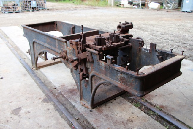 |
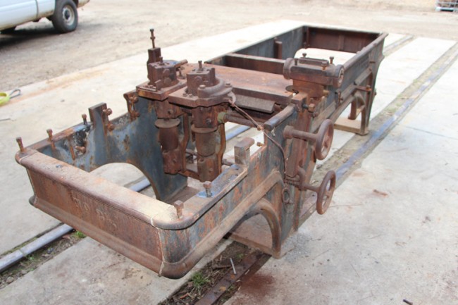 |
Unfortunately, I have another long week of traveling at work this week as I have a meeting to attend in Oregon. My manager was gracious enough though to let me take a couple of extra days off work toward the end of the week though and I am planning on taking advantage of this rare opportunity for me to be in the Pacific NW to do some sightseeing and visit with a few OWWM'ers while I am in the neighborhood. That part I am looking very much forward to!!! But, this will mean that I will once again not be able to do any work on the matcher project until I get back home late next weekend (Saturday - my most productive day for OWWM work - will be a travel day this coming week).
Next on the agenda is to get the side heads off as well as the whole elevation mechanism for the top cutter head. Both are pretty complex mechanisms and everything is really rusted in place. I am anticipating the better part of a day just finishing up getting those parts off. After that, I can start cleaning up and painting the main casting and then start cleaning up the smaller parts and putting it all back together - one piece at a time...