Page History: Unisaw Bullet Motor Repair
Compare Page Revisions
Page Revision: 2012/01/18 02:00
'THIS PAGE IS STILL UNDER DEVELOPMENT. PLEASE DO NOT MODIFY UNTIL THIS HEADER IS REMOVED'This page shows some of the main internal components of a single-phase Unisaw repulsion-start/induction run (RI) "bullet" motor. The page covers three major elements in troubleshooting and repairing internal components:
- Turning the commutator and undercutting the mica
- Fabricating and replacing the shorting necklace
- Replacing the brushes
The approaches and tools shown in the original entry on this page were done in a hobbiest garage-shop, using moderate level tools such as a lathe, and do not require significant machinist skills or equipment.
Turning the Commutator and Undercutting the Mica
The first place to start when any repulsion-start/induction-run motor is having starting difficulties is to turn the commutator to eliminate any carbon build-up on the copper bars and to even out any imbalances or uneven surfaces. This is a fairly common procedure that only takes a few minutes with the rotor assembly mounted on a metal lathe.
The space between the copper bars on the commutator is a softer, non-conductive material called "mica". In order to ensure clean contact between carbon brush surfaces and the copper bars, the top surface of the mica should be slightly recessed below the surface of the commutator bars. After turning the bars down, a user often needs to then remove a small top layer of the mica to create that recess. This process is called undercutting the mica.
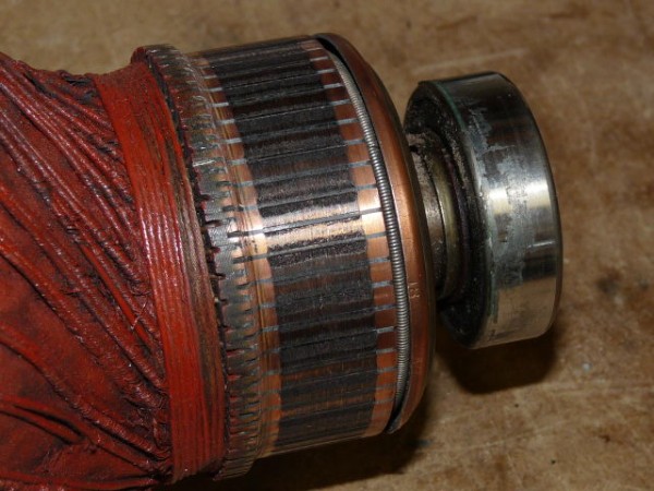
Here is the commutator end of the rotor from a 1hp RI bullet motor. The carbon build-up on the copper surface is obvious, and it's also apparent that the commutator has been turned down several times over the many years.
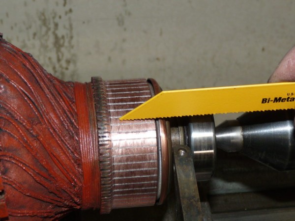
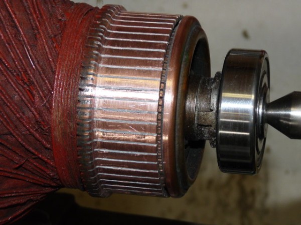
After spending a few minutes on the lathe turning the commutator, it is much cleaner and smoother. However, in this instance, the surface of the mica has also become essentially flush with the top of the bars. Depending on the size of the gap, you can use a small blade and hand cut the grooves lengthwise. In this case, the photo below shows using the tip of a metal blade from a reciprocating saw.
Once done, the commutator looks far better than it did half an hour earlier.
Fabricating and Replacing the Shorting Necklace
The "shorting necklace" inside the commutator is often one of the most common failure points on a Unisaw RI bullet motor. It is also one of the most troublesome parts to locate for replacement. The following discussion shows how to remove the shorting necklace, assess its condition, and one way to fabricate a new shorting necklace from extension spring stock.
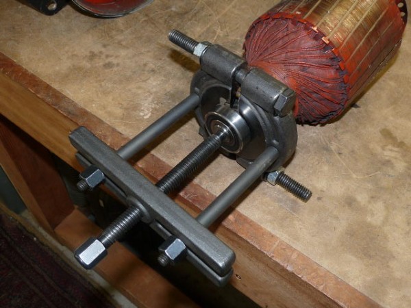
Start by removing the bearing on the commutator end of the rotor assembly.
Behind the bearing, the necklace and contact ring assembly is held in place by a very strong and tight snap ring. There may be different designs of the snap ring, but regardless, this part is often difficult to remove due to its awkward location and its tension. A pair of snap-ring pliers are an almost essential hand tool needed to get the ring loosened from its anchor groove. Use caution when trying to pry it out with items such as screwdrivers, picks, or punches, as you may damage the part or perhaps even injure yourself if it slips.
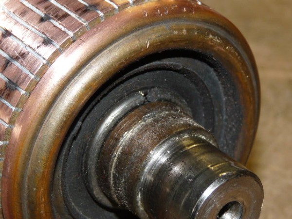
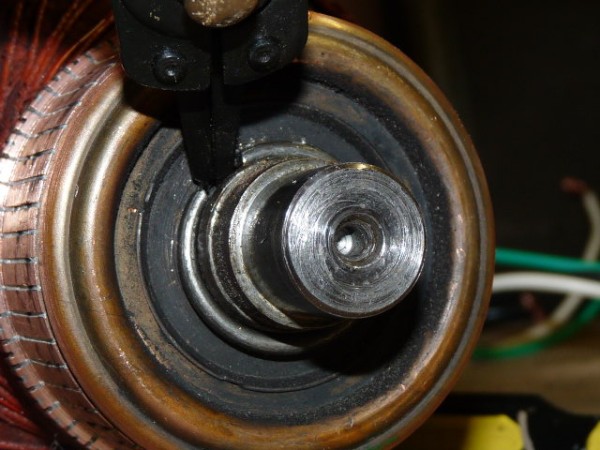
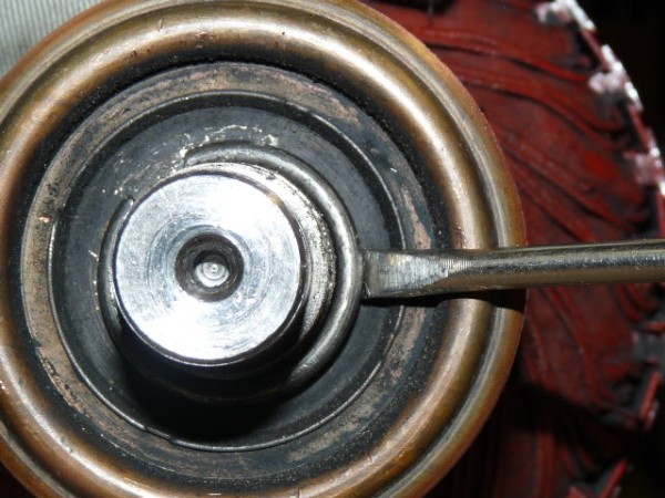
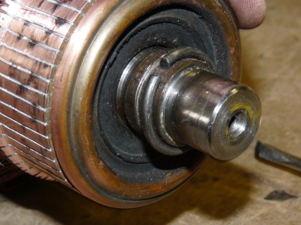
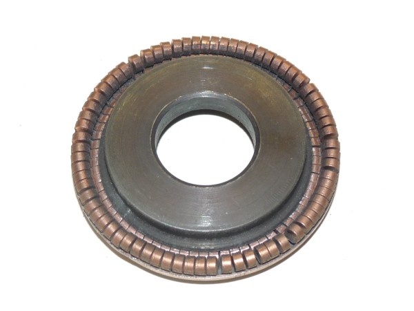
Once the snap ring is removed, the contacts and necklace assembly slips off easily.
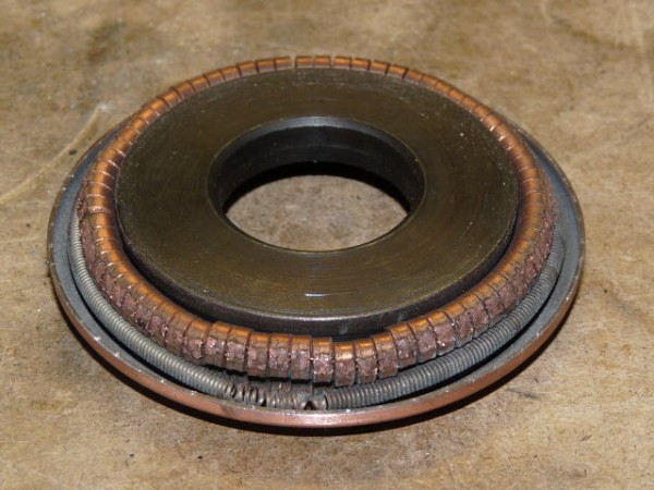
In this case, it is apparent that this "spring has sprung", as seen by the deformed section of the necklace where it has lost its strength to hold the contacts tight together, or "closed."
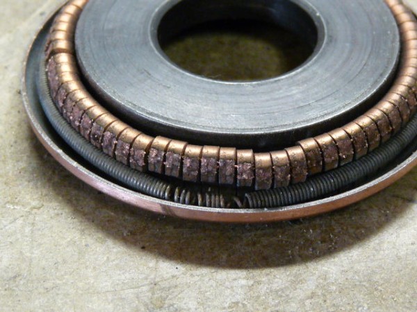
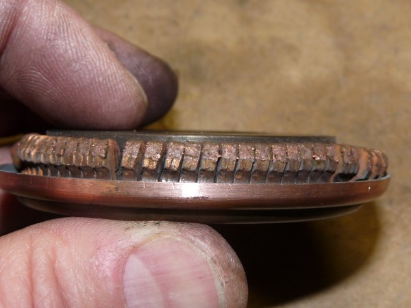
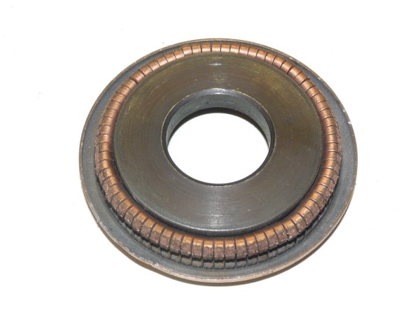
The next three photos show what the contacts look like without the spring, and how they should be positioned respectively when closed and open.
Replacing the Brushes