Page History: Changing the Belt on a Walker-Turner 900 Drill Press
Compare Page Revisions
Page Revision: 2011/04/03 14:11
DEVELOPMENT AND EDITING IN PROCESS, PLEASE BE PATIENT
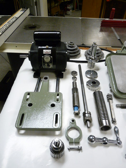
This page shows how the belt can be changed on a Walker-Turner 900 series drill press. These photos were taken during the process of a full restoration of a WT 936, which is a floor model drill press with a production table. The same process can be used on any 900-series machine.
Walker-Turner 900 drill presses used at least two different designs for the upper bearing retainer, on the top of the spindle pulley. One version uses a machined steel sleeve that slips snugly through the head casting from the top and captures the upper pulley bearing. One of these sleeves can be seen in the bottom right of the following parts photo.
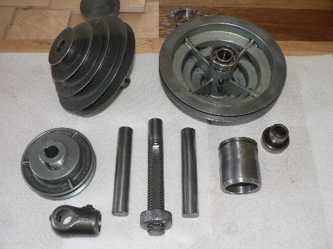 spindle sleeve on bottom right |
The other design, which is what exists on the machine used in this restoration and documentation, has an extended lower end of the spindle cap, which is a single piece that also serves as the upper bearing retainer. This type of spindle cap and bearing retainer can be seen in the upper portion of the following parts photo.
 spindle cap and bearing retainer towards top |
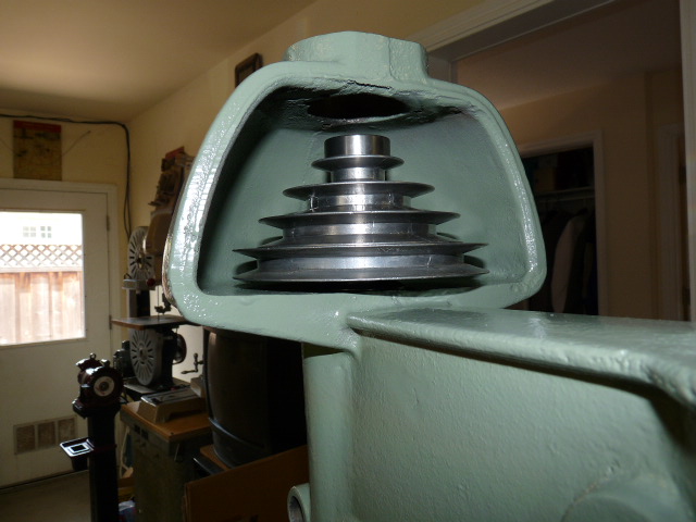
A difficulty in the design of these drill presses, as well as some other manufacturers', is that when the spindle is installed, the spindle pulley is fully captive within the head casting, so a belt cannot simply be slipped over the top of the spindle pulley for installation. Some users get around this difficulty by installing link belts on their drill presses, which can be decoupled at a link, slid around the pulley, and reattached. Others have been able to successfully install a v-belt through the opening on the top of the head casting with the spindle still intact.
The following approach, which shows how to drop the quill and spindle out of the head casting, takes about 15 minutes once you've done it a couple times and is what you would do if you're installing a belt as part of a broader machine restoration anyways.
Start by removing the return spring cover, shown below. Remove the machine screw that bolts the cover to the casting, making sure not to let the cover itself work loose from its stationary position snug against the head.
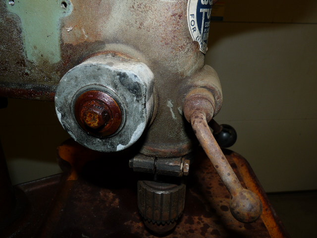 Unrestored return spring cover |
If you look closely at the edge of the cover, you'll see small notches in the cover that fit onto studs that are built into the casting. With a firm grip on the cover, gently pry it slightly away from the casting just enough for the notch to clear the stud. You will feel the tension of the spring working against your grip. Slowly allow the cover to rotate far enough to reengage the next stud in the alignment. Readjust your grip, and repeat the sequence of rotation until the entire tension has been released. When the tension is released and the cover is loose, you can see the end of the coil spring inside where it is attached via a keyslot that slips over a small tab that is screwed into the pinion shaft. Be careful not to allow the actual coil spring to slip out of the cover, or you will find yourself having all kinds of problems getting it back in sometime later when you're reinstalling everything.
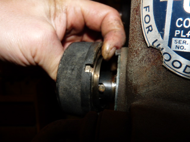 Return spring being loosened |
Slip the end of the coil spring off the tab, taking care not to snag or break the spring itself. If you find a WT 900 where the return spring seems not to work, it is often caused by a problem with this slot/tab intersection -- either it has slipped off or the spring itself may have been broken. It is possible to cut a new slot in the remaining end of the coil and reinstall. In any event, in this case the coil slot can be removed from the pinion tab and set aside. This is the inside of the return coil spring.
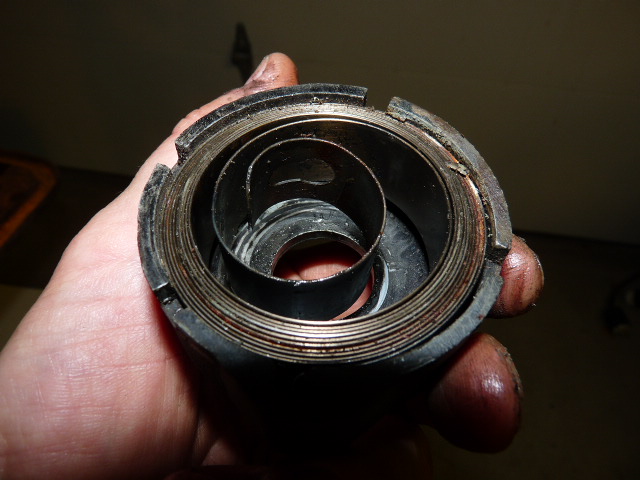 Return spring coil inside the housing cover |
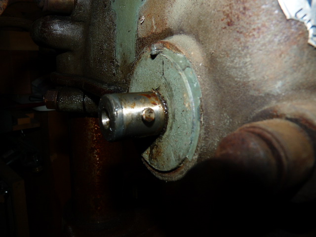
This is the tab that screws into the pinion shaft. It should not be overly tight and should unscrew easily to remove.
 Spring tab on pinion shaft |
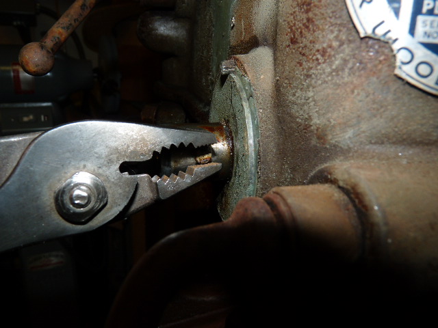 Removing the pinion tab |
At this point, the pinion shaft is ready to be pulled out of the head casting in the direction of the handle. Before doing so, though, you need to ensure that it does not simply drop out of the head once the internal rack-and-pinion gearing is disengaged. Two approaches are recommended: locking the quill lock lever and raising the table up to where the chuck or spindle nose rests on the table. These can then later be moved to allow control when removing the quill.
 Table raised to hold the quill in place |
Now you can gently pull the pinion out of the head casting towards the handle side, which also frees the quill to be removed.
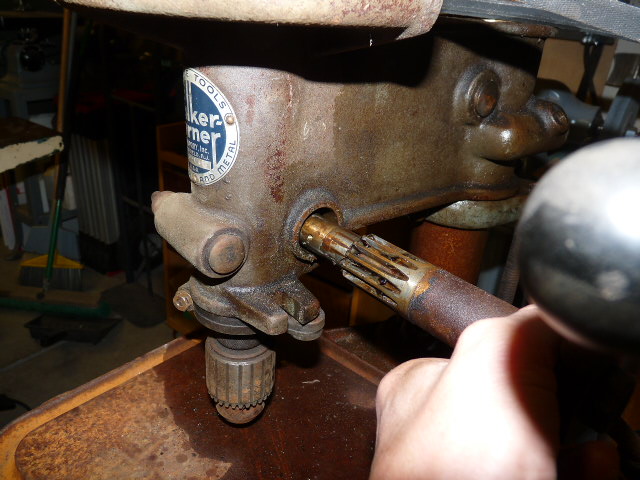 Pulling the pinion shaft |
With a grip on the quill, swing the table out of the way and loosen the quill lock. The quill and spindle will slide downwards as far as you need to go. If you are removing the entire quill for clean-up or maintenance, it can come all the way out.
 Removing the quill and spindle assembly |
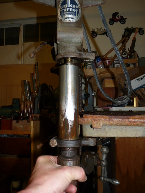
If you are only changing the belt, it only needs to come far enough for the top of the spindle to open a gap above the upper bearing in the head casting.
 Spindle top clear of casting to insert belt |