Page History: Yager/K2000 parts list and dismantling
Compare Page Revisions
Page Revision: 2010/06/28 16:37
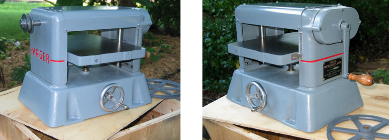
Yager Thickness Planer parts list
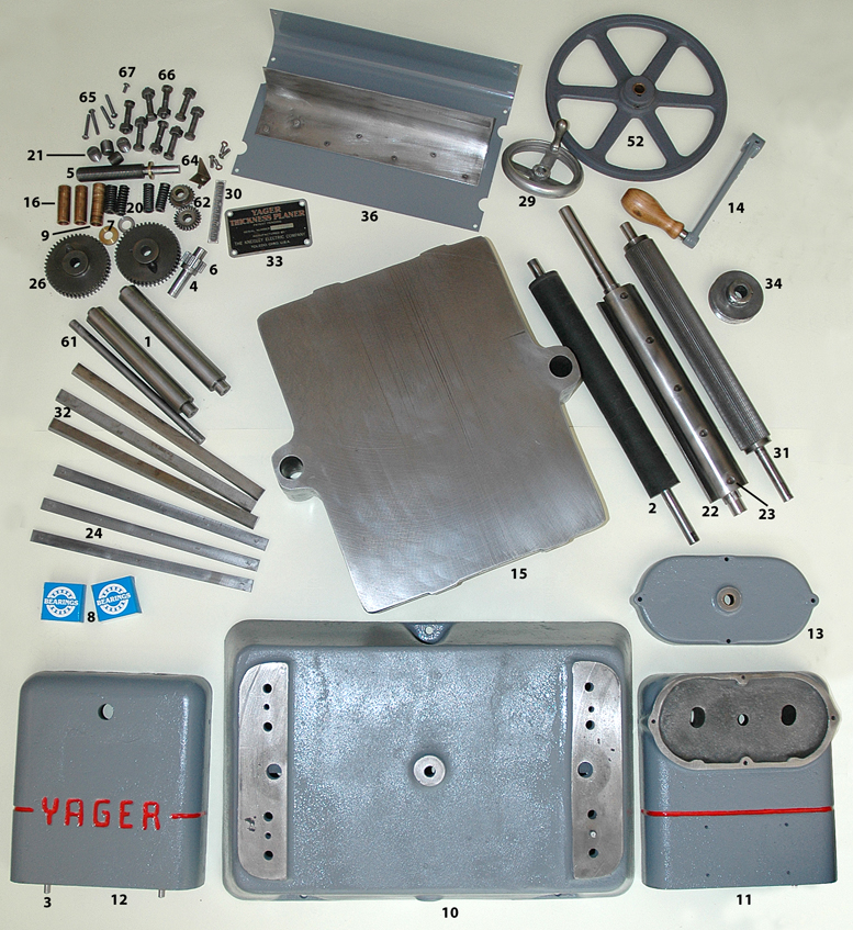
1 Guide Pin (Table)- 2
2 Outfeed Roll (Rubber Covered)
3 Dowel Pin- 4
4 Pinion Shaft Pin
5 Table Adjusting Screw
6 Pinion Shaft for FP-25 Gear
7 Brass Table Washer (Thrust)- 2
8 Cutterhead Bearing- 2
9 Infeed and Outfeed Roll Bushing (Short)- 2
10 Base Casting (Grey Iron)
11 Right Side Casting (Gear Side)
12 Left Side Casting
13 Gear Cover Casting
14 (Optional) Feed Roll Handcrank
52 (Optional) Feed Roll Driver Pulley (8A x 1/2” Bore)
15 Table Casting
16 In and Outfeed Roll Bushing (Long)- 2
20 Compression Spring (Feed Roll)- 4
22 Cutterhead (Cylindrical)
23 Cutterhead Screw (5/16-24 x 1.2 Spline)- 15
24 Cutterhead Backup Plate (Plain)- 3
26 Infeed and Outfeed Roll Gear -2
29 Handwheel (Aluminum for Table Raising)
30 Indicator Scale
31 Infeed Roll (Steel-Serrated)
32 Planer Knives (Plain)- 3
33 Nameplate
34 Cutterhead Pulley (2-1/2A x 5/8” Bore)
36 Chipguard
61 Handwheel Cross Shaft
62 Mitre Gears (for Table Raising-Steel)- 2
64 Indicator Scale Pointer
65 Gear Cover Casting 10-24 x 1 1/4” Round Head Screws- 4
66 Side Casting 5/16-18 x 1-1/2” Hex Head Cap Screws- 8
67 Cutterhead Bearing Retaining Screw
Steps in taking a Yager apart
The K-Line planers are probably the simplest owwm to work on. I am not very mechanically oriented but I found the restoration mostly common sense decision making. I would suggest that you take reference photos during the disassembly process. You will use them. The parts are shown below and parts list are at the wiki.
Take the sheet metal chip breaker off the top and remove the 4 compression spring screws and springs.
Just so you don’t get cut, remove the knives and back up plates from the cutterhead.
Disassemble the handwheel, cross shaft and 2 miter gears from the base.
There are 8 bolts holding the upper castings and parts to the base. Remove these and carefully tap out the 4 guide pins holding the sides to the base. That will give you access to the table and 2 rusty table guides. Turn the large table adjusting screw by hand and the table should slide up and off the guides. Tap out the 2 guides from the bottom of the base. Use scotch brite to clean out the 2 guide holes in the table. Scotch brite and polish the guides nice and shiny and coat with paste wax when you put the planer back together. The smoother these 2 guides, the easier the table will adjust.
Take off the gear side cover casting and remove the 2 feed roller gears. Use a rubber mallet to separate the 2 side castings, cutterhead and feed rollers. There will be a screw holding the gear side bearing you will need to remove first.
Check the in and outfeed roller bushings. These get pretty chewed up over the years. Replace them if needed.
Remove and replace both 88503 cutterhead bearings (treat yourself and call Lynn at Accurate Bearing)
That’s the basic break down. Take some time to remove all rust and gunk. The paint on yours looks good, but repainting is an option. Assemble everything in roughly the same order. Grease the feed roller gears. The handwheel/miter gear assembly are adjusted by the seat of your pants method. If the two gears are making a grinding sound/feel when you turn the wheel, you will need to adjust the gears slightly to get them running smooth. Lightly grease the gears.