By Stephen Thomas
Copyright © 2003 Stephen Thomas - All rights reservedI started woodworking during the late 70's in an area along the Mason-Dixon line between Pennsylvania and Maryland in a region where small job shop millwork had a deep and illustrious past, and a professionally rigorous attitude toward the craft. Just prior to that time, there was a "sash and door plant" in about every third town of any size, and a "planing mill" in nearly every second one. The expected basic complement of equipment was a jointer, planer, bandsaw, variety saw, shaper, mortise machine, and tenoner. One could work wood lots of ways and make money at it too. But at the end of the day you were a rank dilletante without the tenoner and shaper and knowlege of how to tool them up.
I believe that the reason single end tenoners have all but disappeared from small shops is due to the somewhat complex nature of the tooling required to use one effectively; and the supposed difficulty with maintaining it. The machine is capable of magic with the right tooling and operator. It can rapidly produce accurate lock miter joints of several styles, finger joints, french dovetails, cope end profiles for moldings, lap miter joints, saddle joints, saddle miter joints, and the list goes on. I personally feel that not only is mortise and tenon joinery essential to cabinetry and furniture, secure and self locating for the parts; but in most cases it is faster, overall, than other methods with similar expected durability. Since tenons is the first thing one generally plans to make with a tenoner, it is worth having a few methods in the repertoire for sharpening them.
Millburys are made and fit out for ease of low tech maintenance. As I have noted in the list postings, the easiest way to keep the tenon heads sharp is to periodically dress them with a big (12") mill bastard file, and test the profile by rotating the head against a flat, straight piece of hardwood clamped to the table. See where the head hits, and file until both knives hit the whole way across, being sure to keep an good amount of relief. When the knives are equal and true, stone them with an india slipstone to remove the burr and put a keen edge on. If you get in the habit of keeping after them before each "major" job, it is not at all hard to keep the machine sharp, true, and in tune. One advantage of this method is that the knives are always dressed to make a cut parallel to the table surface, exactly as is desired.
Periodically, however, there will come a time when some more aggressive attention might be necessary or desired. Much like gumming out a saw, you can touch up and touch up for sometimes years, but there is going to come a time when the knives need reset or the back relief becomes too scant to be an easy hand filing project. The first order of business is, as mentioned, to reset the knives if necessary. An important consideration is how the knives project axially ("past the end") in relation to the spurs. The spur pocket in the cutterhead is milled deeper towards the bore so the spurs project out a bit at the tips. This gives some clearance to the flat part of the spurs. Ideally, the knives will be set so the tips do not protrude past the spurs axially. Also, the edge of each knife will be at a slight angle so the tips cut and the rest of the edge does not rub. It is best to reset the knives while the cutterhead is still on the tenoner, and before removing the spurs. A block of wood can be clamped to the table to just touch the ends of the spurs. Then the knives can be loosened and reset out to some indicator for projection, and also aligned with the block so as not to drag at the heel nor project past the spurs axially. Once the knives have been set and locked, remove the spurs, as they will be in the way for the grinding operation and will need reset to the new cutting circle in any event.
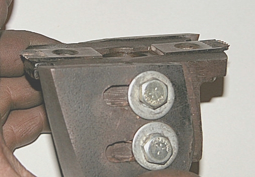
As a side note, as soon as I could make them myself, I threw out the ridiculous pieces Millbury used for spurs, and made a set of hardened fluted spurs. These cut cleaner, last longer between tough ups, and are easy to sharpen. Just file or stone a bevel on the inside edge.
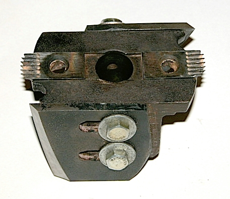
I do not know what the factory knife projection is "supposed" to be. My machine came from a former sash and door plant in Rockville with the knives set out about 1/2". I have used settings from about 1/8" to about 3/8". Nothing stated here should be construed as advice to set the knives to any particular length for any particular application. Generally speaking, "shorter is better" for lots of mechanical reasons. But you are on your own as far as the final call.
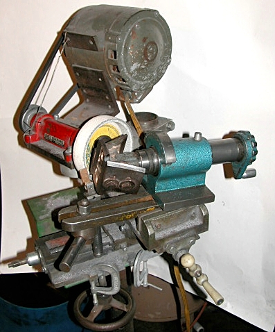
There will be two primary steps to the grinding process. The head will need "spun in" to generate a cylindrical cutting path on the knives. This will actually also make a sharp edge on the knives, but they would not cut in the intended use because there is no back relief. Spinning in generates a cylinder, and hence a true profile along the edge of the knives by which they may be referenced for the second step; further grinding to create the relief and finish sharpening the tool. There are several ways to conveniently generate the cylinder. If there is a way to mount it, a spin index with sliding quill can be used to traverse the tool past a pedestal grinder, surface grinder, or tool and cutter grinder while simultaneously spinning it. If a tool and cutter grinder is available, the workhead can be used to spin the tool, while traversing the table of the machine to move it past the grinder. A spin index with a quill that can be slid in and out axially will automatically carry the tool in a path aligned with the axis of rotation, and hence generate a cylinder. On a T & C grinder, the work head needs to be aligned with the axis of table traverse, both vertically and horizontally, or it will generate a cone, not a cylinder, on the work piece.
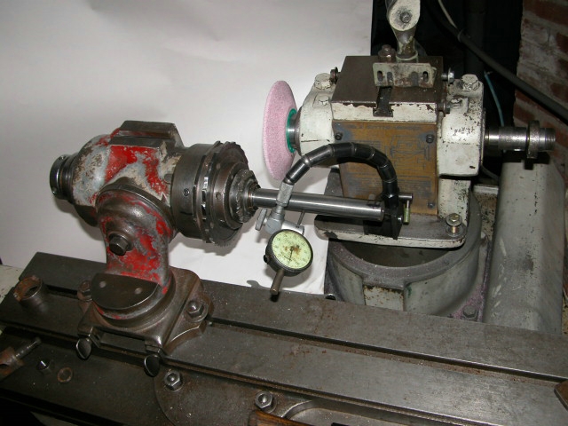
To align the work head, insert a collet and a reasonably accurate test bar (ground drill rod) and indicate the test bar while adjusting the work head tilt and rotate axes so the indicator reads the same when the table is traversed "several" inches. The test bar should first be rotated to indicate the high and low side (mark with a magic marker). Then mark a point halfway between these, and rotate the workhead so all readings with the indicator stem are along this null point. It may be necessary to do a couple interations between vertical and horizontal to get the test bar tracking accurately. The micrometer table swivel feature can be used on a tool and cutter grinder for the final refinements horizontally.
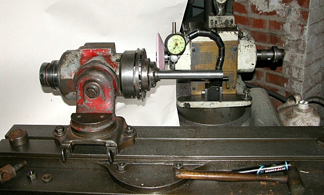
After the head is indicated in, a tool arbor can be placed in the collet to hold the work. In this case it was a short bar of 1" stock turned down to 7/8" with a flat to mount the Millbury tenon heads jsut as they would be mounted and aligned on the machine.
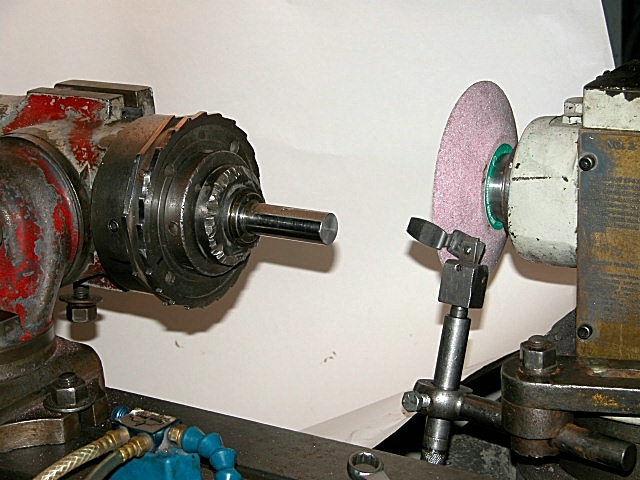
The head can be spun by hand, as I did the first head.
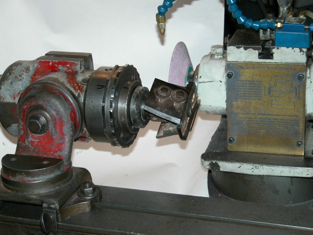
Or it can be motor powered to spin automatically while the operator runs the table back and forth, as the second head was done.
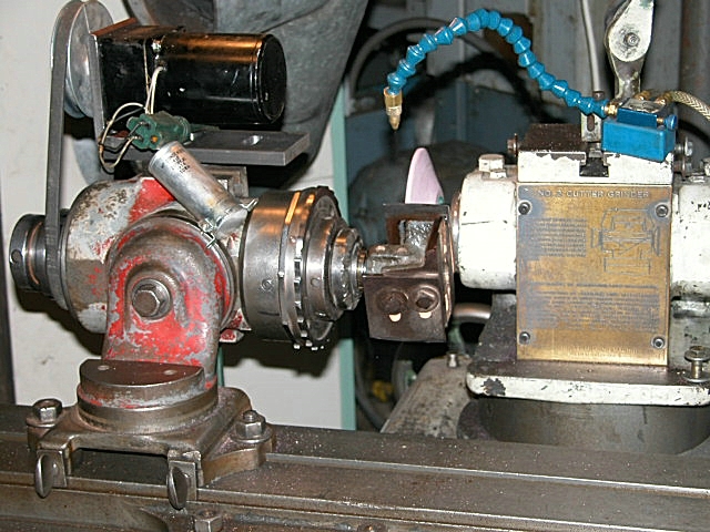
Use a coarse wheel (46 grit) about J hardness. Take small infeeds (.002" - .005") untill the knives clean up the whole way along each edge (photo). Then do a few passes with only .001 or less infeed to be sure the wheel is not wearing faster than the knives and generating a slight taper.
Once the cylinder is generated, each knife edge will be located to the grinding wheel along a rest positioned to guide it.
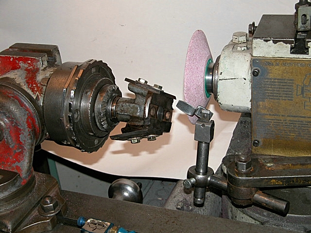
It is convenient if the rest has screw adjustable length (height) adjustment. The rest in the pictures has "micometer" length adjustment by means of a knurled wheel at the bottom of the stem. What will confound the novice and expert alike is that every time something is postioned, it will affect some other part of the set up and cause something else to need redone! I used an offset rest as being most convenient on the tool and cutter grinder. This one has a gently curved edge, which may be ground or filed to suit the application. It needs to be positioned so the contact point of the knife edge is just under its contact point with the grinding wheel. As can be seen in photo, the rest needs to be slanted a bit as well to accomodate the helix angle of the cutter.
In fact, in the case of millbury (and some others such as powermatic) tenon heads, the only true helix on the underside (flat side) of the knives is right on the sharp edge. Hence, there is a bit of extra finesse needed to get this edge always tracking at the right point. Raising or lowering the tooth rest, e.g., will affect the position, as will tilting or swiveling the rest. I personally choose to grind the back relief right up until only a thin land of the original surface from spinning in remains right at the sharp edge; then finish by filing and or honing. More adventuresome types can try their luck grinding past this point and keeping the cutting edge true as each pass develops a different tracking path on both the tool and the rest. It is possible, I just find it more efficient to spend the effort differently (i.e., finish sharpening by hand).
I eyeball the relief angle.
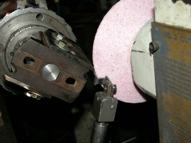
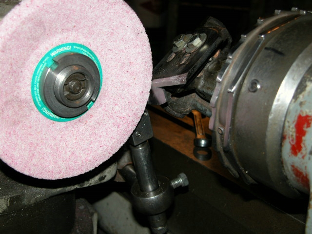
Here, only the spin grinding is done. I am eyballing it to the wheel position while adjusting the grinding wheel height and the tooth rest height until the result "looks right" for the expected relief. With long years of experience, I have a fair eye for what works for the intended application. I don't know how (or am too lazy to try) to explain it on this type tool where it varies with the width across the tool. Look at lots of tools. Aim for a "healthy amount" on this style tool, cutting in shear across the grain. An acute sharpness angle is effective. "More" relief is acceptable farther back toward the heel of the bevel. Less "should" be more durable, but actually will not cut as freely and will cause you to have to sharpen more often. But don't take my word for it. Experiment and use your own judgement.
When cutting on the periphery of the grinding wheel, the relief angle can be adjusted by raising or lowering the wheelhead (grinding wheel), or by raising or lowering the tooth rest, or by a combination of these adjustments. In this case, once the toothrest is set, it is best to only raise or lower it to refine the path the sharp edge tracks. The path will change as the tool in fed in to grind it. Here, i have stopped to see if the relief is developing as expected.
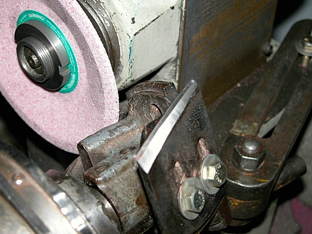
Adjust the relief angle by raising or lowering the wheel head. Again, infeed about .002 to .005 after doing both knives each pass. Keep an eye on the angle, and where the tool is tracking. As mentioned, I skate up near the edge, but then leave a margin for hand finishing so as not to corrupt the reference profile generated by spinning in. I take a few very light finish passes to be sure both edges are the same and leaving the least safe amount for hand work.
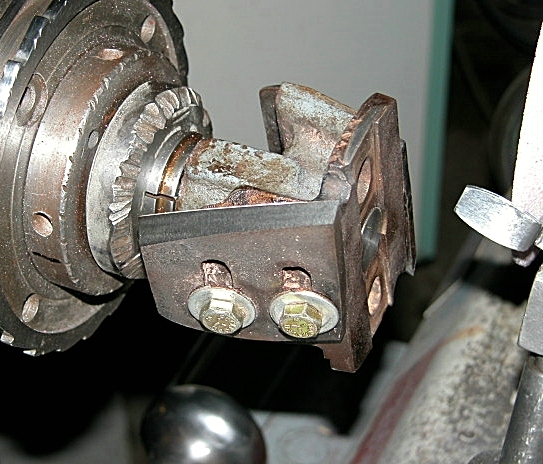
Before owning a tool and cutter grinder, I once sharpened the tenon heads using a cheap import spin index, and a much modified home-made pedestal grinder with an import cross slide vise for the table and infeed. When I made this rig perhaps 15-20 years ago, tool and cutter grinders were valuable machines costing several thousand dollars for even derelict models. Now, perfectly good tool and cutter grinders seem to litter the streets in some neighborhoods, so it would not be worth the time and effort to do a home brew of this primitive nature. Use the time to get some overtime at work, and buy a factory machine for less overall effort. But for old times sake, and as an example, I decided to do the bottom tenon head on this rig.

The typical import spin index does not quite have enough travel to fully pass a millbury head. This can be remedied by making a sleeve (spacer) to go over the collet draw tube and extend it out from where it seats on the spindle; thus allowing the spindle to extend inside the casting. This spacer is just visible in the photo, back between the crank handle casting and the spindle. I used a piece of black pipe, and cut the spacer about 7/16" long. The crank handle will have to be moved out (loosen the set screws) on the drawtube to allow the draw tube to reach far enough in to grip the collet with the spacer in place.
The set up is very similar to the original, with the exception that the "old" rest did not have micrometer length adjustment, and the rest surface was mild steel instead of the bronze used here.
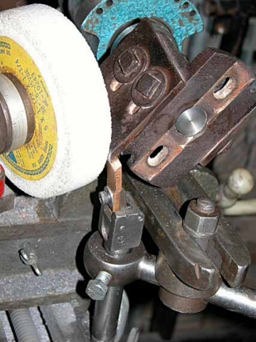
I don't think it makes any difference. The most frustrating aspect of this arrangement was that it was at the limits of capacity and travels. During intitial set up, something would be set "perfec!" only to discover that a screw, or vise handle projection, or grinding wheel nut, or any one fo 5 other things, was now hitting something it should not. With patience, some judicious filing and a few salacious imprecations, everything came together, and the actual grinding was easy. I did get a fair start and realize the relief angle was a bit more aggressive that even I prefer.
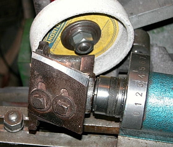
I corrected the clearance by raising the tooth rest gradually for infeed, as raising table caused the vise to hit the wheelhead support arm elsewhere (sigh). So this tool has a sort of primary and secondary relief.
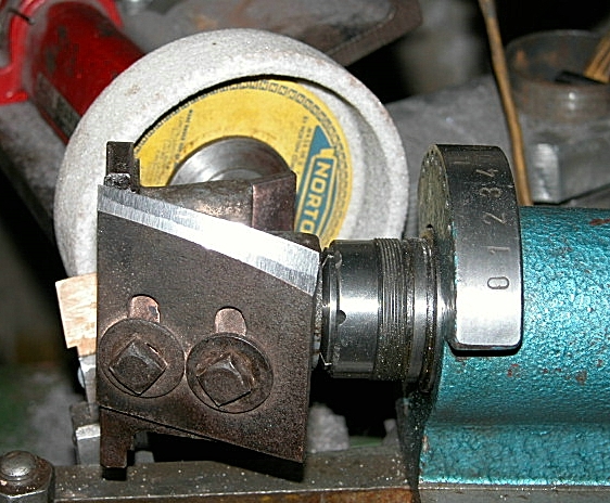
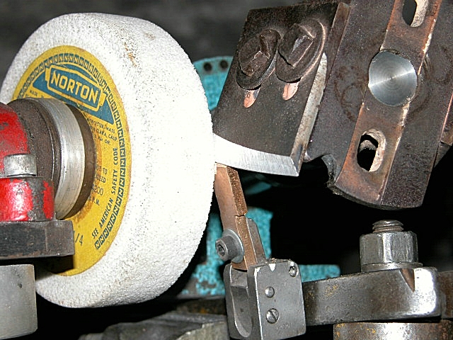
There is absolutely no harm for this style in this application. There are even some advantages. BTW, the blueing on the end of the blade in photo 18 is not from the grinding. It is left over from rubbing on the wood shoulder in a cut and demonstrates the need for clearance in this area when setting the blades in the tool body.
Note that the wheel shape is not an important factor in either grinding set up. In each case, wheel shape was chosen for convenience, not some "technical" reason. Grit and hardness are the critical factors (46 J). Mist coolant was used to spin in the heads, but is not essential. The relief grinding was done dry.
One final note: As sharpened above, the heads should now be true cylinders at the sharp edge of the knives. Sadly, due to wear in the machine components, improper machine erection, and/or vagaries in Millbury's manufacturing process, it may happen that when mounted on the machine spindles, these cylinders might not be perfectly parallel to each other, and may or may not be parallel to the surface of the table. It is still worth a check before running the first real project, to compare the cutting circle to a flat, straight board clamped to the table. If there is a gross discrepancy, the machine may need leveled. I use a good optical level ("transit") for machines of this type and bigger. All 4 corners of the table ways need to be in the same plane. Milllburys are susceptible to twist from not being leveled and erected carefully. The table ways may need shimmed. Or you can get out the big sharp mill bastard file and do a little compensating on the heads.